Monday, December 30, 2013

Back to the Drawing Board, and One More Time!

Okay, now I'm really getting myself into circles.  First, I came up with a design where the modules all went into a cart that stored them.  Then I went with an all-in-one design where the module had full bench work, scenery, lighting and an overhead valance.  After my first design showed some obvious structural flaws, I then went to a compromise where instead  of having a "shadow box" design, I added a support halfway to the back to provide leverage.  However, that design for me was second rate, and not exactly what I was looking for.  Now I'm back to my second design with a new perspective.  Instead of using heavy plywood, I'm going with light plywood and 1x2 lumber to create a truss that distributes the weight of the modules when stacked in a manor that doesn't tear apart any joints.

So below is a summary of my previous designs:


First design I had simple modules that would be lightweight and fit into a cart.  I had planned for about 3 modules per cart with an additional box for buildings and land forms that had to be removed, 1 for each module.


Then I had the idea, "why not just have everything within the module and stack the modules like containers on a ship?"  And behold, my second design was born.  The problem with the design is that the plywood frame alone would be too weak, and additional support would add weight.


Then came the idea to use light dimensional lumber (1x2, 2x2, 1x3) and build a frame such as above.  Then add lightweight plywood to sheath the sides and backdrop.  While this design is okay, the backdrop, curving towards the audience at each end, would look awkward when attached to other modules.  So I gave design number 2 one last try and viola!


Each bracket, instead of using plywood alone, will use 1x2 lumber to make a truss frame.  That frame is then stabilized by being sandwiched between 2 cut pieces of 1/4" plywood.  The result, I'm predicting, will be a much stronger frame that can hold more weight. Will I dance on it?  No, but I can at least stack something on these.

So finally, I've come to the solution I was looking for, and now I can proceed with bench work design.

Saturday, December 28, 2013

More bench work design

More thoughts on the module design:

I did not want to add a frame or bracing to the front of the module because it would break up the layout into a series of scenes. I needed to have support to keep the module stable and strong. The solution was simple, put away the plywood and go with dimensional lumber.

My design is based around framework from 2x2, 1x2 and 1x3 lumber:


The blue represents 2x2 lumber which gives a sturdy vertical support along the backside. The red represents 1x3 pieces that are the main supporting braces for both the scenery base and for the overhead.

The green represents the 1x2 pieces which are secondary support for the 1x3 braces. The 1x2 and 1x3's are combined at right angles to make the familiar L girder bracing popularized by Linn Westcott. However, instead of L girders spanning the full length of the module I instead use the girders as cross braces.

The main difference between this design and the previous design is that instead of a 30" overhang, I plan to have a vertical 1x2 with bracing about halfway down the cross braces on each end. Structurally, this cuts the overhang roughly in half and the brace will give the back framwork some leverage that puts the lumber under tension rather than compression. This design allows for the trains to pass in front obscured, resulting in an uninterrupted view of the layout.


A curved, panoramic backdrop for each module instead sets the scene. One thing I left out of the diagram is that there would be several 1x2 cross braces along the bottom framework which will support the foam scenery base.


The addition of pink or blue foam on top of the cross braces provides a solid and light scenery base. Additional layers can be added to give a varying ground elevation within each module.


Each module can then be completed with very light plywood along the top and possibly the sides and bottom. The 2x2's along the back will do a good job of protecting that side by itself.


The addition of track, scenery and structures plus a lighting system in the valance completes the module. The design protects everything that is within the module while also making the layout look more professional. The backdrops, curving towards the front at each module end, frames the scene while also allowing trains to pass obscured. I'd prefer that the space between the vertical support and the front of the layout be enough that two tracks could be laid down, allowing for sidings to be constructed.

Saturday, December 14, 2013

List of items needed so far:

Expect to see this list as it is updated, but this is a general 'shopping list' for items I am going to need to purchase for this layout:


  • rail
  • turnouts with accessories such as switch stands
  • ties
  • rail spikes
  • tie plates?
  • wire
  • solder
  • rail joiners
  • wire connectors for between modules
  • a power supply or power system
  • pine 1x4's
  • plywood
  • wood screws
  • clamps or bolts to secure modules together
  • 2x2's
  • foam board
  • rollers or casters(?)
  • lighting system (tube or rope lights?)
  • fabric for skirting
  • fabric or canvas to cover open areas of modules when in transport
  • paint or photo for backdrop
  • backdrop and fascia material (hardboard?)
  • paint for ground cover
  • roadbed
  • ballast
  • ground foam, turf and other scenery materials to represent dirt.
  • material which makes good grass (static grass?)
  • materials to make both coniferous and deciduous trees
  • either material to build railroad cars, or railroad car kits
  • paint and possibly airbrush for models
  • lumber for buildings
  • rocks, frocks, plaster casts of rocks?
  • a vehicle or two to represent time period (1870's -1920's)
  • animals and people where appropriate
  • details, details, details...
  • specialty tools for certain tasks
  • to be continued...

Module revisions.

As I worked out the details in my module design which would have included a cart or two for module storage, I happened upon another solution which saves materials.  Instead of having simply a module with a scenery base, the design I worked out below includes a backdrop and overhead framework to protect the trains and all the buildings.  I like this design much better, and as I work through the details I'll refine it.  I used the same dimensions as my previous design, 30" width and a 96" length.  However I also incorporated a 24" overall height of the backdrop.  Below is a cross section of the design:

The framework has a 2" thickness, and the scenery base consists of a minimum 2" thick piece of foam board represented by the pink.  Subtract 4" for the frame and 2" for the foam and I will have 18" of vertical height in the module.  While this may seem tall, when thinking in terms of 1:20.3, this would barely house a full two story building.  Thankfully, with the exception of large mining towers, no buildings were built over two stories, especially on steep terrain with nothing but soft lumber as a building material.  For the trains, I can have my porter run and still have another 9" of clearance between the roof of the locomotive and the bottom of the overhang.  with 1:20.3, the 3ft gauge cars are still somewhat short, nothing really sticking up more than 10" off the track with perhaps the exceptions of cabooses (cabeese) and passenger cars, which my railroad will have few of anyways.  I could go taller, but 24" seems to best fit when dealing with 4x8 sheets of plywood.  My one alternative is to rip the plywood into strips and build the entire module from the stips of plywood, but I'd rather cut out larger pieces that are more structurally sound.

One other problem that I anticipate is the possibility that the wood cannot support any weight on top of the modules.  For this I do have a couple solutions: use cabinet grade hardwood plywood and reinforce the frame pieces with strips of plywood to help carry the weight of additional modules or storage boxes on top.

The following are good things about this module design:

  • Buildings do not have to be taken off the module if secured properly.
  • This design incorporates a backdrop to set the stage
  • The layout can have it's own lighting system, thus ensuring an adequate amount of light anywhere the modules are set up at.
  • Layout can be divided into individual scenes if desired.
  • A simple cloth or canvas skirting to go around the open sides of the module will help with protecting against foul weather during transport.
  • Modules can be built with strong plywood and still be very stable and light.
  • Modules can now be stacked without the need for a separate cabinet.
  • The addition of a backdrop and overhang will draw attention to the trains and their stage which depict the Colorado wilderness.
  • The addition of such features also makes the layout camera friendly by blocking out glare from the large spotlights often found in show areas plus the backdrop frames the scene much nicer than the back of my head in the operating pit or even much worse things like a dirty, dusty, and grimy ceiling of a large structure.
  • This part isn't so much an exclusive feature of this design, but it is still a plus.  With this module style I must be in front to operate the trains, so I can mingle with visitors, point out details and keep guard over my equipment in front of the layout rather than hiding behind it.  This feature may also be a detraction for those who simply want to site quietly and read a book while their trains go in a circle.  
Besides what was already mentioned in the paragraph above, there are a few downsides, just like any design:
  • If you don't like operating from the front of a layout, being in back is possible, but your line of site with your equipment will be obscured.  Besides the possibility of derailments and stalled engines, it will be easier for equipment to be broken or stolen by visitors without anyone noticing.  While I have never had any equipment broken or stolen, there is always that chance, especially at larger shows.  Keeping track of everything is even harder if you are a one man show, which I anticipate I will be for much of the time.  While I can stand for the duration of time a show is in progress, and I can go without food for most of it, this design is not for those who simply wish to sit down and watch the trains run.
  • A barrier must be in place.  Some shows have them, others don't, I personally would rather have a barrier for two reasons: 1) since I must operate the layout from the front, a barrier system gives me space to move around without being in visitors' way. 2) this barrier, though ineffective against small children and the adults who really want to get personal with the layout, for the rest it gives an obvious but not intimidating reminder to respectfully keep their distance and enjoy the layout.
  • Lack of headroom.  I can't have any grand scenes with this system, but that's okay, for now I don't have room for any dramatic canyons or towering mountains.  If I ever do go with something eye catching and large, it is no big trick to simply make one module that lacks an overhead frame.  
  • Curved modules will be impossible, but corner modules will be possible, just more difficult to build.  I eventually want 8' diameter curves for larger rolling stock, but for now I am fine with 4' diameter curves since I have small locomotives and rolling stock.
Aside from that I can't think of much else that would be a problem.  Before closing this post, here is a depiction of the module design in the best 3D that Microsoft paint can offer.

The next item on my planning list is to decide how to support the layout on legs.  After that I will need to develop a budget for the bench work on what I want to do for a project.  If anyone has any suggestions, I'd love to read them in the comment section below.  Thank you!

Saturday, November 23, 2013

Geology, Geography, and the like...

I'm a firm believer that if you want to capture a certain area correctly, you must do research.  As I've progressed in my modeling studies, I've found myself increasingly dependent on maps, charts, and other websites which don't say much about the railroads themselves, but rather thoroughly explain what the terrain looks like, the plants and animals which live in the area, how wind and water shapes the land plus, but less importantly, the geology of the land.  When I mean geology, I'm not talking about statistics, numbers, important points, and research conducted by geology professors who old PhD's. but rather simply what types of rocks are present.

How do all these things relate to the model?  Well, just as there exists prototype information about the railroads, towns and other man made masterpieces; there also exists a vast wealth of information of the land, a sort of natural prototype information is what is needed.  Why you ask, because knowing what the land looks like, what trees grow there, what rocks can be found there, even what animals inhabit the area help a modeler capture the feel and the area being modeled.  Think of it this way, you don't model North Dakota with towering mountains, but you also don't model Washington State with no trees.  This is an extreme example, but my point lies there.

So if I am to capture Colorado, specifically Clear Creek county, I will need to look at the natural features of the area.


  • Terrain in Clear Creek is generally steep mountains made of igneous rock (granite type rock) with some sedimentary in areas.  Valley floors with generally be strewn with large rock debris in all sizes, however some silt will still exist, coming from the annual spring melting.  Moving closer to the continental divide, the rocks become newer, sharper, and have less top soil. 
  •  Near the top of the canyon by Georgetown, clear creek is broken into three tributaries in addition to the creek; clear creek runs southwest before continuing straight west to the divide, the West Fork will continue straight west running parallel to Clear Creek, but to the north, Bard Creek sits in between the two in it's own small valley.
  • Major plant species to be in the area will include various bushes, but evergreen trees (a mix of fir, pine, and spruce with the occasional juniper or cedar) inhabit the steep slopes.  Joining the bushes by the water, small stands of Aspen trees exist.  since aspen roots are interconnected, stands of aspen can start near water, but will ranch up the slopes a ways.  For slopes which face the sun (generally southfacing) the terrain is less populated by trees and more by meadows with flowers in the summer months.
  • Animals aren't really that important for the landscape, but if I were to include some animals in the more wild parts of the layout, black bear cougar, Rocky Mountain Elk, and a bison or two would be my choice.  In addition, squirrel and chipmunk plus raccoon and skunk can make appearances in the towns modeled.  And of course, people are in the town too!
So what I have to model are steep slopes with flowers where there would be sun, and dense forest in the shade or where a lot of water may come through.  If near the creek, boulders with some silt will be in and around the creek, making the perfect habitat for a variety of bushes and shrubs, but Aspen will dominate that area.  Towns are usually near water, so most towns depicted will be only a few feet fro water on the model.  Mines may be all over the slop of the mountain, and so miner's cabins along with the supply stores and the mines themselves will be among the tall stands of evergreen trees and the alpine grasslands near the very top of the canyon.  The bottom of the canyon will generally be a very tight and steep climb, but the top will be more open and leisurely.

Where do I get this information?  To start with, here is a map of the region:

Image taken from the Department of the Interior website.

However there is also plenty of other useful information besides just a map:

With these two sources, nearly everything I need to know about the landscape, plants, animals and water are now known and noted on this blog.

Thursday, November 21, 2013

Module Work

G scale modules are something not often discussed in the model railroading community, however such a subject is essential when working with a portable layout in such a large scale.  It is true that in smaller scales such as N or HO, one 4X8 or smaller will work perfectly as a display railroad at a train show.  However with G scale, the absolute minimum that could be used for a continuous layout would be 5X8 feet, which often won't fit in anything but a pickup truck with a standard 8' bed.  Not to mention, this sized layout for G scale is incredibly small due to G scale's size.

By studying the module standards in place for various other G scale modular railroads including the Sundance Central and the G-whiz gang, I determined that for this project, two different modules should be built:

The module on the left will be the A module or the straight module. Dimensions of 30" width with an 96" yields 20 square feet of area to work with.  in 1:20.3 scale, I can comfortably have a single mainline and up to two additional tracks to provide for sidings, spurs or for a yard.

The module to the right is the B module or the curve module.  The end plates will be 30" wide to match the straight module ends.  overall maximum dimensions for this module is about 45" wide  and 71" long.

The diagram in the upper right is a cross section showing roughly how the legs and braces will be attached.  I plan to have the legs to have a cross section that looks like angle iron, making the leg stable in both side to side as well as back and forth motion.  with the straight module, I plan to have the legs swing up, and one pair may have casters so that the module is easy to set up and move with one person.  I do have to face facts, at the present moment I'm a one man show, and I couldn't even take my dog to college, so really I've got friends, but no one who is close enough to share this hobby with.  Not saying I'm lonely, but I do have to remember no one is around to help.

The next problem is transport.  These modules will require some sort of cover.  I've seen this idea before, and I know it works to build a cart specially designed to hold modules.  in HO scale, these carts can hold up to 12 modules!  In G scale, there is another problem, each module needs at least a few inches of vertical clearance.  buildings, trees, and land forms over a certain height will have to be removed.  I plan to have one tote for structures, cars, and people with another tote for vegetation for every module.  Thus, each module will have at most 2 totes to accompany that module.

Why this standard?  To start with, this keeps the operation simple and keeps the modules from looking over crowded.  Secondly, totes take up space too.  What I've found with previous modular designs is that when in transport, the modules themselves can be neatly packed, but the totes and additional materials always seem to clutter up the back seat, trunk, trailer, or even the passenger seat!

As for the cart: I've worked out the cross wise dimensions below:

Skinned with 3/8" plywood and framed with 2x2's and 1x2's, this cart will be light, but will still require casters for movement.  Each module will have a unique frame that allows it to slide in the cart like a drawer.  Should the cart tip over or need to be laid on it's side, having modules that can't move around will be much safer.  From bottom of the cart to the top, the interior space will be about 56" tall by a hair over 30" wide.  Exterior dimensions will be 60" by 34".  With three modules being stored in the cart, each module will have a space of 17 vertical inches.  Subtract 3" for the frame and another 4" for the scenery base, each module will have 10" of clearance for permanent fixtures.  To be on the safe side, trees and hills over about 8" will still be packed away. All buildings that required substantial time or money to have on the layout will also be removed for the buildings' safety.

Another cart will be used for curved modules, and differ by first only housing two modules instead of three plus it will be shaped differently to best protect the unique shape of the modules.

I want to do a test run by building 3 straight modules and 2 curved modules which would be cheap to build and a manageable project for a summer.  Two carts are also manageable in the back of a truck, SUV or a trailer.  Main reason for the cart is so that the modules won't need an enclosed trailer, simply keeping out moisture is all that is necessary to ensure that the modules can arrive at their destination in one piece and dry.

What can I expect for scenery? Below is a conceptual track plan:


Monday, November 18, 2013

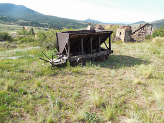
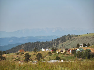
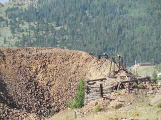
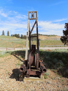
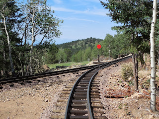
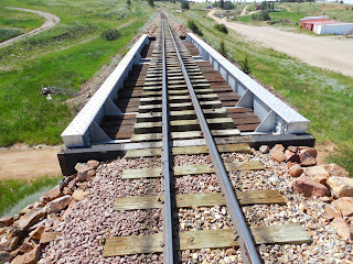
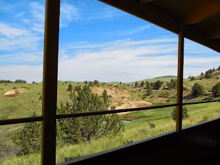
Photos of Cripple Creek


Cripple Creek Colorado is one of the few places where you can walk through history.  Strewn around are signs of the past, giant hoist towers, solid gold bins